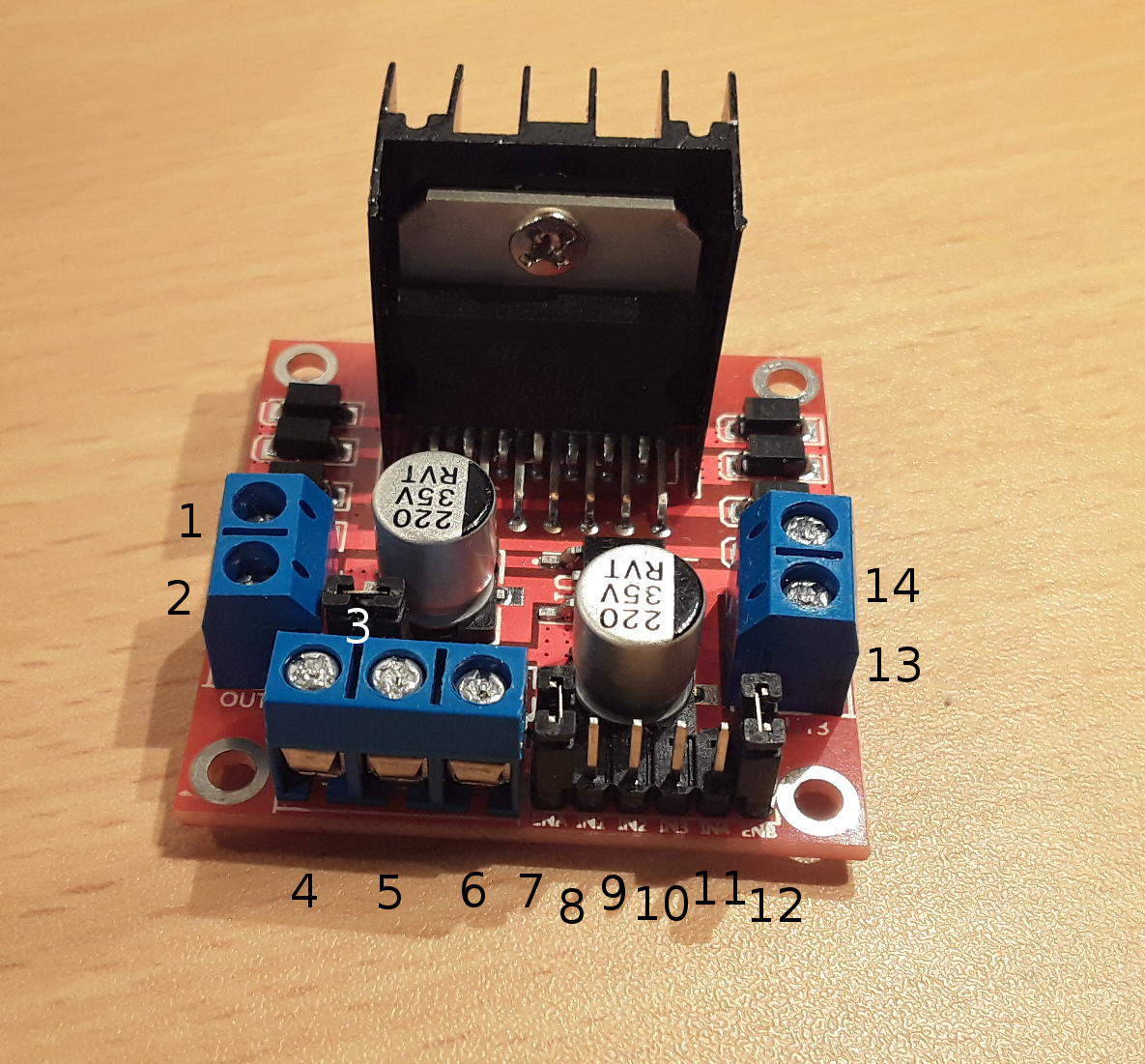

This input logic controls the direction of DC motors connected to the driver. A motor driver module takes the low voltage input from a controller like Arduino. It is commonly used in autonomous robots and RC cars. The higher the duty cycle, the greater the average voltage being applied to the dc motor(High Speed) and the lower the duty cycle, the less the average voltage being applied to the dc motor(Low Speed)Ī motor driver module is a simple circuit used for controlling a DC motor.

The average voltage is proportional to the width of the pulses known as Duty Cycle. PWM is a technique where average value of the input voltage is adjusted by sending a series of ON-OFF pulses. A common technique for doing this is to use PWM (Pulse Width Modulation). The speed of a DC motor can be controlled by varying its input voltage.

H-Bridge – For controlling rotation direction.This can be achieved by combining these two techniques. In order to have a complete control over DC motor, we have to control its speed and rotation direction. We well take a look at basic techniques for controlling DC motors and we will learn how to control DC motors using the L298N driver and the Arduino board. In this Arduino Tutorial we will learn how to control DC motors using Arduino.


 0 kommentar(er)
